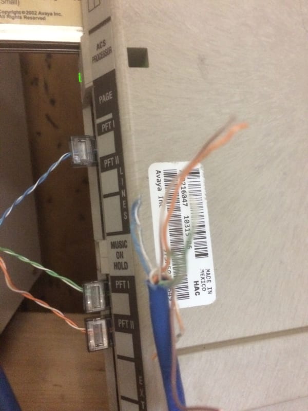
Ok here's the trouble I'm currently having. I have a partner acs (Not sure on version looks like either a 6,7 or 8). It has 3 lines coming out of it - 3 single pairs connected to 3 jacks on the acs, all from 1 cat5e.
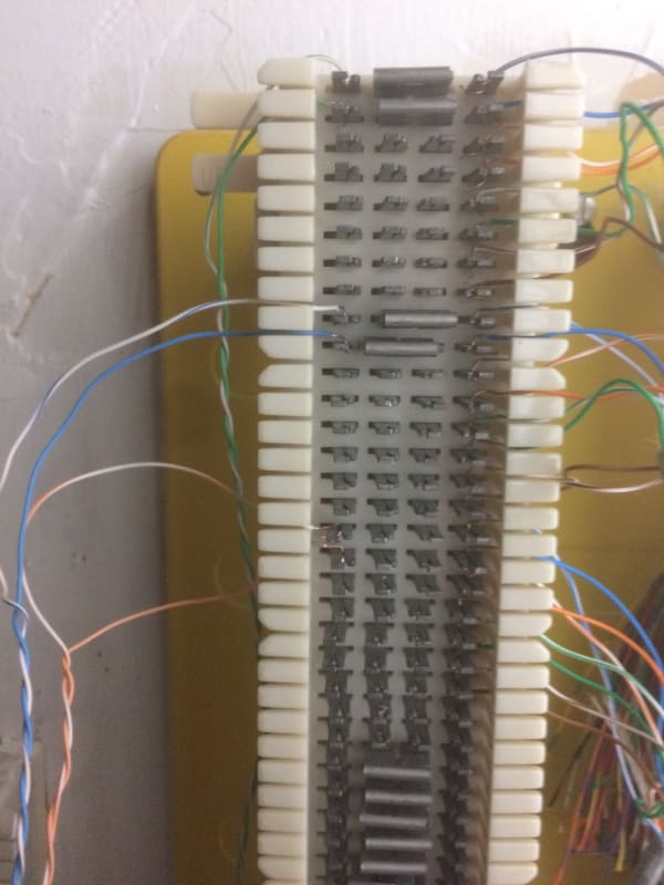
I then have a 66 block as follows: right side 3 cat5e cables all the way down (w/bl,w/o,w/g,w/br) connected to the wall jacks. 3 single pairs from the telco are connected on the left side, bridged to the jacks, all 3 connected at the w/bl spots. This is enough to get a dial tone when connecting a phone to any jack, and call in/out.
What doesn't work however is the ACS. no matter how/where I connect the wires, I can not seem to get power to the Avaya phones. For refence, it's a single cat 5e split w/bl in 1 jack, w/o in a 2nd jack, and w/g on the 3rd. (in the acs). The other end of the cat5e is supposed to be connected somewhere on the 66 block, but anywhere I connect it, I can not get power through. Note: This *did* work once but the entire system/setup had to be moved, and now it won't connect.
My basic question here is... how is it SUPPOSED to be wired? Looking at tons of diagrams and otherwise, suggests the following: main line jack in top section (line), other 2 in exts, and then the 2 single pairs punched in and cross connected to... somewhere? In the old set up they were simply punched in directly on top of the telco lines, but this doesn't work, so now I'm at a loss.


![[smile] [smile] [smile]](/data/assets/smilies/smile.gif)
![[love2] [love2] [love2]](/data/assets/smilies/love2.gif) "FEATURE 00
"FEATURE 00