Tek-Tips is the largest IT community on the Internet today!

Members share and learn making Tek-Tips Forums the best source of peer-reviewed technical information on the Internet!

  • Congratulations SkipVought on being selected by the Tek-Tips community for having the most helpful posts in the forums last week. Way to Go!

Can anyone help me identify this old phone cabling? 2

Status
Not open for further replies.

danmb

Programmer
May 31, 2003
31
0
6
US
Hi,

So occasionally I'll come across an old phone installation that's being replaced, and being the pack rat I am, I'll hold on to some of the old cabling.

Can anyone tell me what this RJ11 connector is called, a model number perhaps, who makes it, and if it is still available?

20210924_115641_g6lyen.jpg


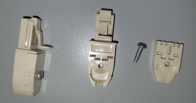
They're useful for checking for broken wires in an existing cable, I can swap wires and test it out without wasting a plug - these are reusable, crimped plugs aren't.

Also these jacks have been around forever, but I don't know the model number or who made them. They come in single line and two line varieties.

20210925_232720_bwg4ga.jpg


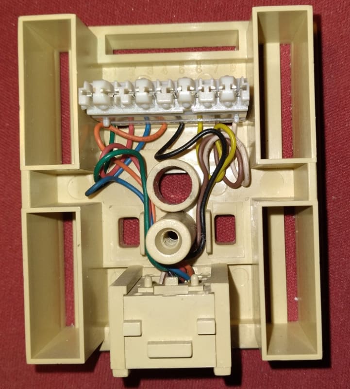
What mystifies me is the wiring scheme - pins labeled from 1 to 8 with Green, Red, Blue, Orange, Black, Yellow, (???), White. Every time I try to wire one of these things with new wire I get it wrong.

Anyone know what the correct pin number to the White/Color color scheme correspondence is?

Thanks in advance.
 
For an Avaya Partner ACS 4 wire system, the wiring would be:

White/orange -> ??? Black pin 5 ???

Blue -> pin 2 - Red

White/Blue -> pin 1 - Green

Orange -> ??? Yellow pin 6 ?????


The first one is a 6p4c "RJ-11" I think Suttle or Reliance used to make them, haven't used them in a very long time. Good for solid conductors.

The second is a standard USOC 8p8c "biscuit" jack, again usually made by Suttle or Reliance or other Western Electric clone. This has 110 style punchdown for termination.

Pin
1 Blue Ring 3
2 Orange Tip 3
3 Black Tip 2
4 Red Ring 1
5 Green Tip 1
6 Yellow Ring 2
7 Brown Tip 4
8 Slate or White Ring 4

The above Pair assignments for Tip/Ring are from memory and sketchy wikipedia sources.

The cover usually has the pinout embossed or as a sticker inside it.
 
Hi,

Thank you for your reply.

I dumped out my whole used cable box onto the floor and sorted through it.

Lo and behold I found one of these damn jacks in its original wrapper. The 2 line model.

It's made by Leviton:

Leviton Type 104 (41046-IDA) 0F20E0 6 conductor

A Google search gets some hits on Ebay

s-l1600_1_gwy0gc.jpg


That's the one!

The wiring scheme on this jack is absolutely maddening. It actually has a wiring diagram on a piece of paper which, to anyone used to Cat5 or above, is incomprehensible.

If you look at the 110 punch down block inside the jack, the positions are numbered left to right 1 to 8, but what those numbers correspond to is beyond me. It's definitely not pinouts.

The jack's color scheme on the 110 block is:
1 - Green
2 - Red
3 - Blue
4 - Orange
5 - Black
6 - Yellow
7 - Brown
8 - White

So to answer my question, to wire a Type 104 jack for a Partner ACS 4 wire system with Cat5 wire:

If the plug going in to the Avaya end is wired 568B ("split the green"), then on this damn jack,

Jack punch down position / Jack wire color / Cat5 Cable Wire color
1 / Green / White/Blue
2 / Red / Blue
5 / Black / White/Green
6 / Yellow / Green

If the plug going in to the Avaya is wired 568A ("split the orange"), then substitute Orange for Green above, everything else the same.

The Gotcha was, you skip pins 3 & 4 and use 5 & 6. That's why I was going nuts last week.

My network cable tester says pin 1 not there, 2 not there, 3, 4, 5, 6 OK, 7 not there, 8 not there. That is correct. Avaya uses the center 2 pairs.

I'll know tomorrow if the Avaya likes it.
 
The pinout for the punch down is simply White/Blue, Blue/White, White/Orange, Orange/White, White/Green, Green/White, White/Brown, Brown/White.

The wires from the bottom of the 110 punchdown to the jack are set up so the jack is 568-B wiring pattern.

It's not Cat-5, they were used by AT&T for wiring Merlin and Definity station.

Bring the I/W into the jack through the hole in the bottom. Take the Blue and Orange pairs around the post that the cover screw goes into (counter-clockwise as seen in your picture above) and slip into the first 4 slots. Take the Green and Brown pairs and go around the post clockwise and slip into the last 4 slots. Punch them down or just use the caps and snip off the tails.

Those screw shell plugs were also made in 8-conductor, you could terminate a 4-pair I/W with it and plug directly into the station port on a circuit cards.
 
Well, better late than never. For your rj-11 question.


UPC: 091324174713

6p4c Modular Plug for Solid Wire, 10pcs
PI Part #: 6P4C-MK-10

Special Order only available these days.

6P4C-MK-10-1_xhxri0.jpg


A workaround of sorts, but much more available these days.

[URL unfurl="true"]https://res.cloudinary.com/engineering-com/image/upload/v1635746467/tips/screwterminalrj11_hoiflz.webp[/url]

 
Status
Not open for further replies.

Part and Inventory Search

Sponsor

Back
Top