Has anyone here ever attempted component level repair? Two issues. First one should be easy.
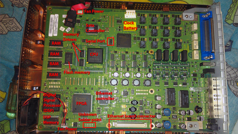
I've got a BCM50 that won't keep the date and time after power down. It always reverts to Feb 6th 2036 and I don't know if I'll live long enough to see the calendar catch up to it![[wink]](/data/assets/smilies/wink.gif "[wink] [wink]") . Taking a look at the board I'd say it's a 99% chance it being that big yellow M4T28-BR12SH1 timekeeper/lithium battery module that's the problem and I see they're still available from places like Digikey and Mouser. Can anyone confirm my assumption?
. Taking a look at the board I'd say it's a 99% chance it being that big yellow M4T28-BR12SH1 timekeeper/lithium battery module that's the problem and I see they're still available from places like Digikey and Mouser. Can anyone confirm my assumption?
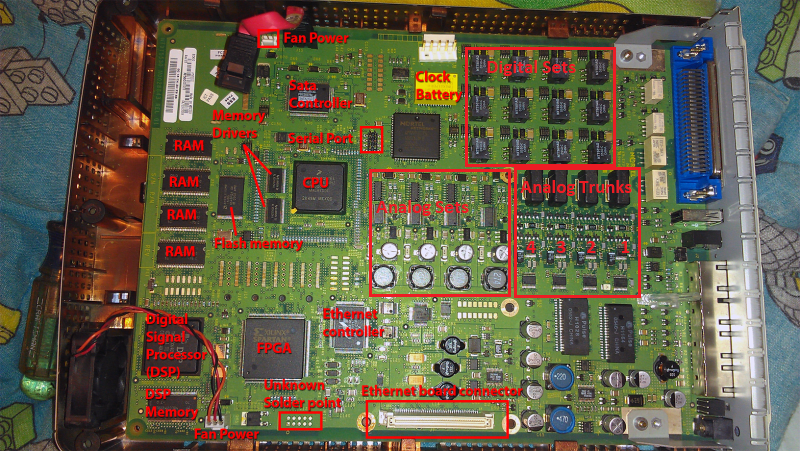
Second issue. I was playing around with my lab unit one day and the amphenol connector came off crooked with the cable end off first and the screw down end still on. I had a telco line connected to line one and after that I couldn't get dial tone on that line and calling it gave a busy a few times and then calling again I could hear ring back on the calling end but the BCM wouldn't detect the ring. So that line is pooched but the others are ok. I did a close inspection of the board and saw two areas that had identical circuits times four. One must be the trunks and the other the four analog extensions. Who's who? Looked up the SI3050 and SI3019 data sheets and they're the ones that do the ring detect and off hook etc so they're the ones. Determined that U2 and U3 are associated with trunk one. The data sheets for them show that the 3019 is the one that interfaces with the outside world (my fingers) so I'd wager that's it or some of it's support circuitry. The data sheet has an application circuit that looks very similar to the components on the BCM so that will be of help. Haven't launched into it yet as I haven't done a lot of smd (surface mount device) component repair, I come from the era of through hole which I'm very familiar with. My smd success rate is about 50% but that 50% would be the smd's come off![[smile]](/data/assets/smilies/smile.gif "[smile] [smile]") . I'll have to practice on some circuit boards before working up the nerve for the real thing. I'll post my results when done but it may take a while (weeks/months) as I have to locate and order parts.
. I'll have to practice on some circuit boards before working up the nerve for the real thing. I'll post my results when done but it may take a while (weeks/months) as I have to locate and order parts.
Unfortunately the only BCM50's I've ever run into with bad motherboards are one's I screwed up myself. Everything else is always power supplies and hard drives.
Sure would be helpful if there were schematics for the BCM50 motherboard somewhere!
I've got a BCM50 that won't keep the date and time after power down. It always reverts to Feb 6th 2036 and I don't know if I'll live long enough to see the calendar catch up to it
. Taking a look at the board I'd say it's a 99% chance it being that big yellow M4T28-BR12SH1 timekeeper/lithium battery module that's the problem and I see they're still available from places like Digikey and Mouser. Can anyone confirm my assumption?Second issue. I was playing around with my lab unit one day and the amphenol connector came off crooked with the cable end off first and the screw down end still on. I had a telco line connected to line one and after that I couldn't get dial tone on that line and calling it gave a busy a few times and then calling again I could hear ring back on the calling end but the BCM wouldn't detect the ring. So that line is pooched but the others are ok. I did a close inspection of the board and saw two areas that had identical circuits times four. One must be the trunks and the other the four analog extensions. Who's who? Looked up the SI3050 and SI3019 data sheets and they're the ones that do the ring detect and off hook etc so they're the ones. Determined that U2 and U3 are associated with trunk one. The data sheets for them show that the 3019 is the one that interfaces with the outside world (my fingers) so I'd wager that's it or some of it's support circuitry. The data sheet has an application circuit that looks very similar to the components on the BCM so that will be of help. Haven't launched into it yet as I haven't done a lot of smd (surface mount device) component repair, I come from the era of through hole which I'm very familiar with. My smd success rate is about 50% but that 50% would be the smd's come off
. I'll have to practice on some circuit boards before working up the nerve for the real thing. I'll post my results when done but it may take a while (weeks/months) as I have to locate and order parts.Unfortunately the only BCM50's I've ever run into with bad motherboards are one's I screwed up myself. Everything else is always power supplies and hard drives.
Sure would be helpful if there were schematics for the BCM50 motherboard somewhere!
![[clown]](/data/assets/smilies/clown.gif "[clown] [clown]")