Tek-Tips is the largest IT community on the Internet today!

Members share and learn making Tek-Tips Forums the best source of peer-reviewed technical information on the Internet!

  • Congratulations gkittelson on being selected by the Tek-Tips community for having the most helpful posts in the forums last week. Way to Go!

Advice on protecting panasonic kx-ns5162 doorbell system from lightning surges? 1

Status
Not open for further replies.

Jupiter99

IS-IT--Management
Aug 25, 2020
48
IT
Hi everyone,

I'm seeking advice on protecting my home doorbell system from lightning surges. I’ve had success in safeguarding my network equipment (switches, routers, etc.) using Ethernet-to-fiber-optic adapters paired with a UPS system, but I’m still facing issues with my Panasonic KX-NS5162 module connected to an NS 500 PBX system. Every time there’s a strong storm, the doorbell system gets damaged, requiring a module replacement

Has anyone encountered this issue or found a solution? I’d appreciate any suggestions on surge protection devices, grounding methods, or any other ideas that could help protect this setup.

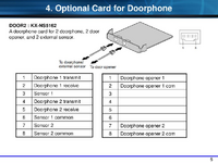
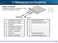
This is the connection scheme, maybe some wires could be protected somehow?
1728301299659.png

Thanks in advance for your insights!
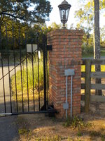
 
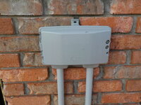
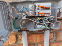
I have the same card in a NS700 with a doorphone at our driveway gate, close to a 1000' away. We're also utilizing the relay contacts to operate the gate. I utilized two-pair direct burial telco drop wire, the jelly ("snot") filled type, with the shielding jacket. I have a telco protector box at each end. I'm not sure exactly what is within them for protectors, I have a ground rod driven at the gate end for that protector. At the other end, the protector is connected to the electric service ground, to provide a common ground point. I have a #6 copper running from the ground bus, in the electrical panel, along the bottom of the wall mounted plywood backboard, and it terminates on the relay rack in which the NS700, a server and network components are mounted in. I do have an additional #10 bonding wire from the NS700 ground screw to the #6 attaching bolt just to be sure I had a good ground connection, as the rack had a very durable paint finish. I have the shield, of the telco drop wire, bonded to the earth ground within each protector, also. Pretty much a standard telco installation.

When a nearby lightening strikes occurs, the phones programmed to ring from an intercom box call, also ring. This is the protectors functioning as they should clamping the pair together and to ground. (A short across the door phone pair will trigger a ring.) We're in east central Alabama. So the thunderstorms are pretty regular and fairly intense. I've had the system in place for a year without issue.
 
Hello and thanks for your thorough reply. Here in Italy we measure cross-sectional area of copper cables in mm² (millimeters squared) as per the IEC 60228. Could you tell me what would be as per the copper cable you have used over 1000' (is that 300mt??)

Thanks!
 
Good Morning:
I'm not sure if you were seeking the cross sectional area of the conductors or the overall cable. Here is a link to the cable I would suggest. It is a six pair cable, rather than the two pair I utilized. The cost difference is typically small and the extra pairs may come in handy, in the future.

I utilized the two pair as I was able to make a heck of a deal with the contractor who was plowing in the fiber drop, for our internet service. The two pair cable would fit, in the shoe of the cable plow, along with the fiber cable, whereas the six pair would not. So I was able to have the two pair plowed in, along with the fiber, for a bargain price.

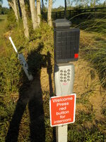
I'd also suggest you paint the "Call" pushbutton a different color. Panasonic always colored them darn near the same color as the main housing, so they are not obvious to folks. I utilized the beige intercom boxes in lieu of a door bell in my previous home. Folks were always knocking on the door, as they didn't see the "Call" button.

Here are some photos of my gate installation:

DSCN2575.JPG


DSCN2576.JPG

DSCN2577.JPG


DSCN2580.JPG
 
Great stuff mate! Thanks for sharing :).

What pins did you use in the scheme below?
1728401186002.png
 
I utilized pins 1 & 2, of the doorphone/external sensor jack, for the intercom box and pins 1 & 2, of the the door opener jack, as the dry contact closure that operates the gate.

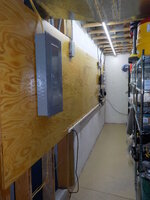
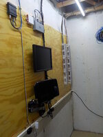
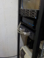
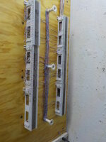
I brought out ALL the PBX jacks to "66" blocks, in which I have a row of blocks for the PBX and another row for premise wiring. I then utilize cross-connect wire and bridging clips to connect the two. This provides far more flexibility in the future, is simpler & tidy. I see your an IT guy. No reflection on you, but I found nearly all IP personnel to have just downright sloppy cable management practices. During my career, I built and maintained a number of Public Safety Access Points (PSAP). I was known for being quite the tyrant, with the in-house IP personnel, about their cable management practices within the dispatch centers and equipment rooms.

We re-located to this home two years ago. It was built in the late '90s and did not have any network cabling. So I utilized the Panasonic proprietary electronic hybrid telephones on the existing CAT3 inside wiring. Even where I fished in wiring for wall mounted phones, I utilized the electronic hybrid telephones. Wall mount kits have become crazy expensive for the IP phones. Thus, why the PBX has a full load of expansion cards. I utilize IP phones in the outbuildings.

DSCN2379.JPG

DSCN2380.JPG


DSCN2382.JPG

DSCN2384.JPG
 
Last edited:
Status
Not open for further replies.

Part and Inventory Search

Sponsor

Back
Top