Example:
Please send the following part and dispatch a qualified tech to replace the part
g650 cabinet 3A. Tech should also check fans and filters to make sure that all
fans are running and blocking of airflow through the g650 is not an issue.
This is easy for an on-site person to identify.
customer or TOS required before part is shipped.
Please find out from customer which fan assembly is required:
700258155-R AVAYA G650 MEDIA GATEWAY FAN ASSEMBLY REFURBISHED 3 screws on btm
700394398-R AVAYA G650 MEDIA GATEWAY FAN ASSEMBLY REFURBISHED 4 clasps on btm
700246671-R AVAYA G650 MEDIA GATEWAY POWER SUPPLY 655A REFURB
700406135-R AVAYA G650 MEDIA GATEWAY POWER SUPPLY 655A RHS REFURB
700394497 AVAYA AHF110 S1V3 TDM Bus Terminator
If this Fan Assembly does not resolve this issue, the g650 itself will need to
be shipped and replaced.
700259724-R AVAYA G650 MEDIA GATEWAY CHASSIS W/O POWER SUPPLY REFURB
CAB-PFL and CAB-TEMP alarms in 3A g650
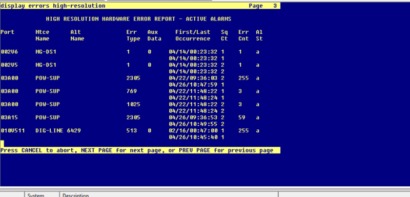
1 (a) Power/Fan Lead Query Test (#1533) MAJ MIN OFF test environment location
a. Error Type 1: The AuxSig lead is active. Run test environment location and
follow the repair steps for Power/Fan Lead Query Test (#1533).
1 FAIL G650: In a G650 carrier, this indicates a failure in any of the following
MOs:
- SER-BUS (Serial Communication Bus)
- POW-SUP (Power Supply)
- CAB-TEMP (Cabinet Temperature)
- PS-RGEN (Power Supply Ring Generator)
Use the diagnostic procedures for those MOs to clear the problem.
1 FAIL
(cont'd)
G600 / CMC1
There is a fan, temperature, power, or voltage problem in one or more of
the cabinets. The power supply's LEDs may indicate the problem's
source.
1. If none of the fans are running, then:
a. Verify 8- to 14-Volt DC power is available to the fan units by
checking the wiring connector. If there is 8- to 14-Volt DC power
at the connector, there should be power to the fans. If the fans
still do not run, replace the fan assembly.
b. If not, then the power unit's fan output is defective or thermally
shut down. Let the power unit cool, and recycle AC input power.
If no fan output, replace the power unit. If the fans still do not
run, escalate the problem.
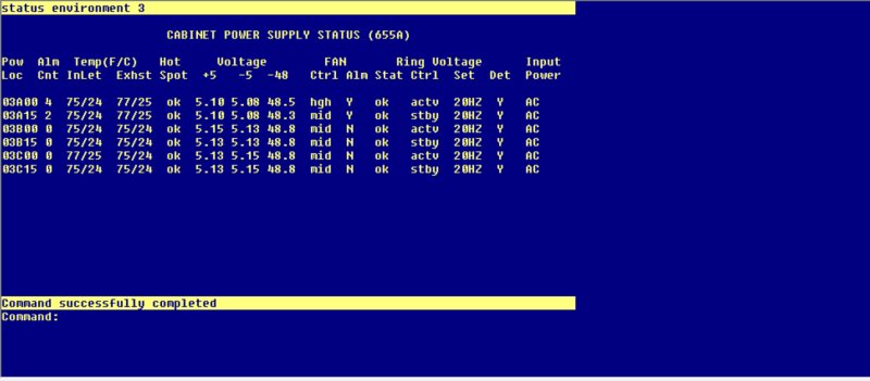
status env 3
recycle carrier 3a15 (standby)
2. If only 1 of the fans is not running, replace the fan.
3. If every fan can be started, wait 5 minutes and rerun the test. If the
test fails again, proceed to Step 4 or Step 5 as applicable.
4. If the fans are not at high speed, measure the cabinet's
temperature at the air intake and the air exhaust at the top of the
cabinet.
a. If the 5- to 600-C criteria is met, there is a problem with the fans
which is preventing the fans from operating at high speed.
Replace the fans. If the fans run at high speed, wait 5 minutes
to give the cabinet time to cool down and, rerun the test. If the
problem persists, go to step 5.
b. If not, the Processor circuit pack is incorrectly reporting this
condition. Look for and resolve every error on these MOs first,
then rerun the test.
5. If the fans are running at high speed, check the following items. Any
one of these could be restricting or redirecting the cabinet's air flow:
a. Check the filter. If the filter is dirty or clogged, it should be
cleaned or replaced. The filter can either be washed with soap
and water or vacuumed.
b. Verify that nothing other than circuit packs are in the carrier
slots that could be restricting air flow.
c. Verify that no circuit-pack blanks or carrier faceplates are
missing. Install and/or replace them as necessary.
d. Be sure the cabinet's doors are properly closed. The doors
must be closed to enable the fans to properly cool the cabinet.
Wait 5 minutes to allow the fans to cool the cabinet. Rerun the
test. If the test still fails, proceed to Step 6.
6. At this point, there should be nothing impeding the air flow, and the
fans should be running at high speed. Check the temperatures for
the 5- to 600-C criteria.
a. If the 5- to 600-C criteria exists, a temperature problem exists,
and the fans (at high speed) should cool down the switch. Wait
5 minutes, then rerun the test. If the test still fails, the ambient
room temperature is probably too high, and the room should be
cooled.
b. If the 5- to 600-C criteria does not exist, the fans are defective.
Replace the fan assembly and rerun the test. Failures can
occur on the Processor circuit pack that are not detected but
that cause many, if not every, environment test to fail. If many
environment tests are failing, the suspected circuit pack,
depending on the system configuration, should be replaced and
the test rerun.
7. There is a problem with the environment of the power system. The
power unit for the cabinet may be defective.
a. Verify and, if necessary, replace the power unit.
b. Rerun the test. If the test still fails, escalate.
--------------------------------------------------------------------------------
G650 fan removal/replacement
This should not be service affecting to replace the fan assembly.
! WARNING:
WARNING: You can remove the fan assembly while the system is running, but you
must replace the new assembly within 60 seconds to avoid a thermal overload.
To replace a G650 fan:
1. Place the new fan assembly close to the G650.
2. Loosen the thumb screws on the fan assembly, and pull it straight out as
shown in Figure 58: Removing the G650 fan assembly on page 292.
3. Disconnect the fan cable.
4. Connect the new cable and position the new fan assembly.
5. Tighten every thumb screw on the fan assembly.
[url=http://downloads.avaya.com/css/P8/documents/003877246][URL unfurl="true"]http://downloads.avaya.com/css/P8/documents/003877246[/URL][/url]
[url=http://www.tek-tips.com/viewthread.cfm?qid=1770867][URL unfurl="true"]http://www.tek-tips.com/viewthread.cfm?qid=1770867[/URL][/url]
PS-RGEN (Power Supply Ring Generator)
G650
The PS-RGEN maintenance object monitors the ringing voltage of each 655A power
supply. The TN2312BP IPSI uses the ring detection circuit on the 655A to monitor
ring voltage for the G650. When the TN2312BP IPSI is used in an MCC1 or SCC1,
the ring detector on the tone clock monitors ringing.
When the G650 is equipped with two power supplies, the 655A power supply on the
left (slot 0) is the primary power supply (master) and the 655A power supply on
the right (slot 15) is the secondary power supply. In normal operation, the
primary 655A provides ringing for the G650. If the primary 655A is unable to
provide ringing to the G650 because it has failed or because of a command from
the TN2312BP IPSI, the secondary 655A connects ringing to the backplane using an
arbitration lead. Normally the ring voltage LED (#5) on the left power supply is
ON and the ring voltage LED on the right power supply is OFF. This changes
momentarily when the ringer interchange test is run. The ring voltage LED will
only remain lit on the right power supply when there is a power supply failure
of the left hand supply or the left hand supply is removed.
Only one 655A power supply provides ringing voltage to the backplane. The other
power supply ring voltage output is isolated from the backplane through a relay
contact.
Refer to Figure 66: G650 Cabinet Environmental Hardware Components for further
information.
Use status environment to obtain:
- Inlet temperature - 655A power supply sensor
- Exhaust temperature - G650 carrier exhaust air sensor
- Hot Spot temperature - 655A power supply sensor
- The system generates a warning at 176o Fahrenheit (80o Celsius).
- The power supply shuts down at 194o Fahrenheit (90o Celsius).
- Power supply output voltage measurements, +5VDC, -5VDC, and -48VDC
- Fan Control - The speed of the fans, either mid (normal) or high (fan failure
or hot spot temperature limit exceeded).
- Fan Alarm - Detection of a blocked or failed fan
- Ring Status - OK, overload, shorted, or failed
- Ring Control - Active, standby, disabled, off (shorted or failed)
- Ringer Setting - 20Hz, 25Hz, or other
- Ring Detection - Reports if power supply detects ring on the backplane ring
leads
- Source of input power - AC, DC, or both
- Input power - Indicates the type of power currently in use, AC or DC
- AuxSig signal status
Note:
If the TN 2312BP IPSI cot get data from the power supplies, the data entries for
status environment will be dashed out.
Use recycle carrier to:
- Shut off all voltage output temporarily
- Shut off ringer voltage output temporarily
Use clear error to:
- Clear the non-volatile source ID cause of the last shutdown
- Clear the serial bus error and time-out counters